
- 2,112I/O signals in the process control system
- 3redundant systems in the control system, each with two CPU 410-5H
- 8CPU 410-5H in total, including the EMS redundant system
- 20+package units integrated via Modbus
Control architecture
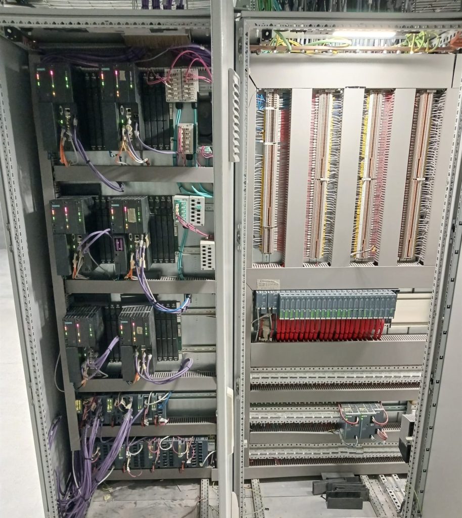
- Siemens SIMATIC PCS 7 with three redundant automation systems in the control system, each with two CPU 410-5H: six CPUs
- A separate redundant system for the EMS, with two more CPU 410-5H
- Two CP 443-1 communication processors in each control system
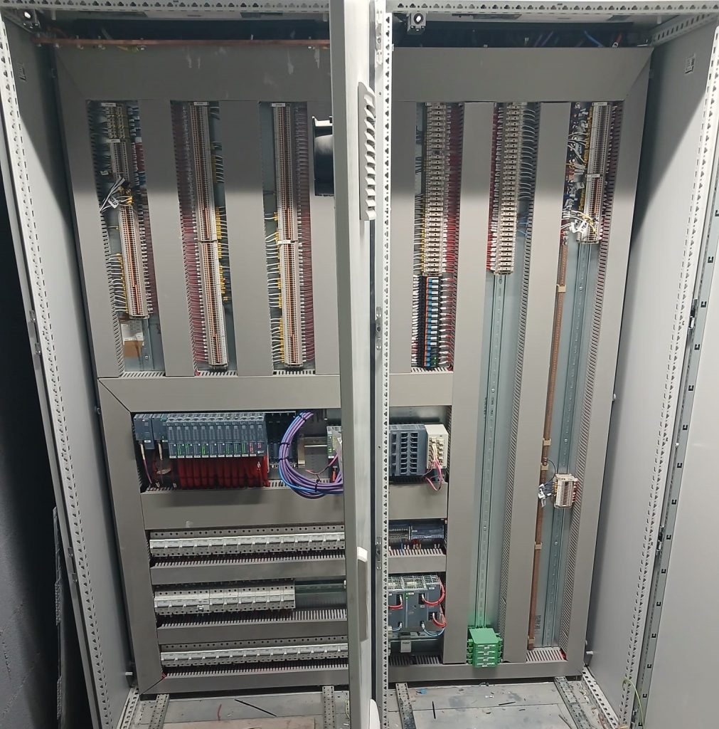
- ET 200SP HA distributed I/O with dual PROFINET interface modules
- Redundant 24 V DC power supplies in the remote stations
- Fibre-optic network with Siemens SCALANCE industrial switches between areas and remote stations
- Two plant networks (Plant Bus 1 and Plant Bus 2) for control and a separate Terminal Bus for operation
- Programming with the PCS 7 APL library
Of the control system’s 2,112 I/O signals, 1,824 are digital and 288 analogue.
Supervision, operation and historical data
Supervision relies on two PCS 7 OS servers, main and redundant, on virtual machines hosted on different hosts, with operator stations and an engineering station. PCS 7 Process Historian stores the historical data and OpenPCS 7 serves and exports it to other applications.
Operators work with process screens and faceplates, with user access and actions subject to their permissions: they manage and locate alarms, consult historical data and trends, export data and view interlocks.
Multi-protocol integration of third-party equipment
The architecture integrates into the control system the electrical installations (main LV switchboards for normal and emergency supply, medium voltage, emergency diesel generator and UPS), the plant utilities (compressed air, boilers and steam, purified water, effluent treatment and gases) and the water and energy meters. To do so it combines several industrial communications:
PROFINET
Distributed I/O and control architecture equipment.
Modbus TCP/IP
Package units and other third-party equipment; gateways from Modbus RTU for serial devices.
M-Bus
Meters, integrated through gateways to Modbus TCP/IP.
S7 connections
Redundant data exchange between the control system and the EMS and BMS systems.
Fibre optics
Communication infrastructure between areas and remote stations.
A piece of equipment appearing in the architecture means it is integrated with the control system, not that it was supplied: many of these units have their own manufacturer’s control.
Network segmentation and Active Directory
MIESA also designed the network and user infrastructure of the control system:
- Design of the network segmentation, with separate operation, control, EMS and BMS networks
- Complete layer 2 configuration of the network
- IP addressing plan for the system
- Design and hardening of the Active Directory for the PCS 7 environment
Coordination with the EMS and BMS systems on Desigo CC
PCS 7 is the control and supervision platform of the PCS; the EMS and BMS systems are based on Siemens Desigo CC, with their own servers. The two domains exchange data through redundant S7 connections.
Engineering and testing
The engineering started from a review of the basic engineering and included the electrical schematics in EPLAN, the wiring and power drawings and the as-built drawings of the PLC cabinets. The planned tests covered dimensional checks, auxiliary devices, wiring checks and simulation of the programming.
Other MIESA projects at Faes Farma
At the same plant, MIESA also developed the low-voltage switchboards and the environmental monitoring system (EMS) with Siemens Desigo CC.
Do you need a Siemens PCS 7 control system?
Whether you are preparing a new plant or the migration of an existing system, tell us about the project. We handle the engineering, cabinets, programming and commissioning with our own team.